Showing posts with label DIY. Show all posts

Monday, March 15, 2010

PROJECT - 4WD Shower System


This is a work in progress so far, but I thought I'd throw up what I've done up to now.

When we were over on Moreton Island at Christmas time, our trusty old solar shower bag sprung a leak. Also, the weight of hanging 20kg bags of water from the top spars of our shower tent took it's toll and broke one of the fibreglass spars. Not to mention that we had to lash the shower tent to our main tent to stop it falling over with so much weight up top - ask me how I know what it was about to do!

But generally, the lack of pressurised water sucked big time. The solar shower had always done us proud, and in the outback even a dribble of water over you washes the dust off and you instantly feel a million bucks. But the sand needed more pressure to get it off you - the dribbling water stream from the bag simply made it stick to you more. So I cracked it with the solar shower, and vowed I'd get something better.

When you're looking at your options when it comes to camp showers, there's a LOT of very different solutions out there, ranging from the fancy to the basic, and from the cheap to the expensive. You've also got to weigh up the size and weight of the various options - if it's too big or cumbersome, you're not going to take it with you. and if it's too hard to set up or takes to long to get going, you're not going to want to use it.

We settled on a heat-exchanger style setup. There are a number of companies who make kits in this style, and they're all pretty similar. You have a 12v water pump to draw water out of a bucket/creek, and pump it through a heat exchanger. It comes out the other end hot, and you plug in your shower rose, and instant hot shower. The heat-exchange is plumbed into the vehicle's cooling system, so running the engine gives an unlimited supply of hot water for showering, or washing up, or whatever you need hot water for. Keeping in mind that the vehicle's cooling system will normally run at around 110-degrees, you can end up with quite hot water (which can catch you out if you're not careful!).

These systems have their downsides - you've got to shower near the car, and you've got to have the car running to get hot water. But they're very compact, since everything mounts under the bonnet, all you've got to take with you is the pick-up hose and the shower hose/rose. And that sounds perfect to me. They're also very simple - no complex, fancy stuff to go wrong. And they're ready to use as soon as you are - no boiling water / forgetting to leave the solar shower bag in the sun, etc.

I had decided to use a Glind unit as they're a local QLD based company, and others have had very good experience with them. There are other options that are very similar - Twine is another Aus-based company that's been doing this for a while, Piranha have their Power Shower setup, and there's a mob called Helton that make heat exchangers in different shapes and sizes, and you supply whatever pump you want. The Glind units seemed ever so slightly better built (6 bolts holding the centre together, instead of 4 on the others for instance), the pumps that were included were a bit better, and their service and response to emails was good. So I was pretty sold on the Glind unit.

The only problem was that, being who I am, I didn't really want to spend $500 on the Original kit that included the big FloJet pump. It's listed as being able to draw water from a creek 10m away and up a 2m incline, and give really good pressure. I figured that pretty much every time I'd be using it, I'd be drawing from a bucket/jerry at the car, and thus could get away with the smaller pump. The pressure and flow rate might not have been as good, but it would be easier to mount under the bonnet. Another tick in the Glind's favour is that the smaller pump (the Little Ripper kit) is a fully marinised pump as well - meaning it's salt-water safe - important if you ever need to draw from a very salty bore, for instance. I found a lot of the others, with their smaller pumps, were not marine pumps.

So that was saving some money right there - the RRP on the Original kit is $500, the Little Ripper, $430. Then I happened to chance across an eBay seller in Bris, reselling the Glind kits at a discount. So I bought a Little Ripper kit from him, for the princely sum of $355. Wonderful - that was much more in my price range, and would do everything we wanted. Maybe not as fancy as the big kit, but that was OK. The next day I received the dreaded email from the seller advising me that Glind were out of stock of the smaller Little Ripper pumps. Rats - knew it was too good to be true. However, the factory was offering to upgrade me to the bigger Original kit for no extra charge! Awesome! Every now and then you kick a goal!

2 days later, the big box arrived at home:


How all of that fitted in that box, I'll never know. I certainly haven't been able to pack it all back away.

Of course, the downside to this was that instead of easily being able to fit the smaller pump under the bonnet, I had to squeeze in the big pump. A fellow on the Pathfinder forum had emailed me photos of his install. He had his pump (the bigger one too) mounted vertically, behind the grill and in front of the radiator. Initially I was going to put mine in the same spot, but the manual that came with the pump was *very* insistent that the pump was not sealed and should be kept away from water. It was also quite clear that the pump shouldn't be mounted motor-down. Now, obviously this other fellow has not had any problems with his set up, and he covers MANY more outback miles that I probably ever will. So I really don't think it matters. But I'd already had a spot picked out for the smaller pump, so I thought I'd see if the bigger one would fit.

An afternoon playing around with cardboard and a pair of scissors produced a workable template, which was easily cut out of some left over aluminium treadplate and bent up.


Pretty, it ain't. In a lot of spots, what looks like me not being able to cut a straight line is actually sections that have been clearanced from the plate to allow it to squeeze in...


...there, using existing bolt locations and without needing to move any of the existing equipment. It's a tight fit...


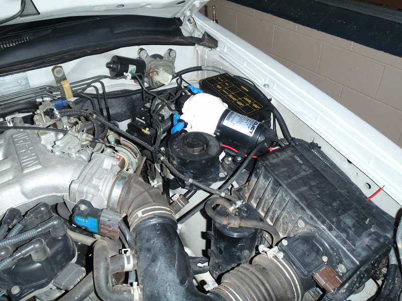
... as well as not having much headroom. Luckily, the angle that it's on mounts the highest part of the pump head inboard of the raised section of the bonnet. Whilst it touches the sound deadening under-bonnet lining (some paint dabbed on the pump head shows exactly where), it actually just squishes the lining a little bit, and still has heaps of room around it. Very happy with how it's turned out. It should be kept nice and dry up there, well away from any water, mud or muck.

We wired in a switch for the pump...


... right next to it, where it's protected nicely in the relay box. Our car is missing the left-most two relays on the top row, which provided a perfect spot for the switch and wiring. The switch has a little green LED on it to show when it's on. It's been wired back to the front control panel of the dual-battery system, and connected through a fuse box to the AUX battery feed.

A few days mucking around with the welder yielded:


A brace of 3 brackets, to hold the heat exchange nice and securely. The last two brackets took all weekend just in themselves - there's no way I could do this as a career - 3 days of fiddling x even a piddly hourly rate would bankrupt anyone!

The end result:


The heat exchanger is all mounted up and ready to go. It's held very securely - the left hand side is rock solid, with only a bit of flex capable on the right-hand side (with the single bracket). I'm hopeful that once the hoses are all connected it won't be a problem at all. It clears all pre-existing equipment, brake lines, vacuum lines and such, and still provides access to the transmission dipstick behind it.

For now, that's as far as I've got, with the heat exchange being fitted to the car tonight. Later in the week I'll need to plumb the HE into the car's heater/cooling system, and bleed any air out of the system and top the radiator/overflow tank. Half an hour spent scrounging through the heater hose bin at Supercheap (and generally making a pest of myself to anyone wanting to get down that isle) netted a pair of VB commodore hoses, which are the perfect shape and length, having a right-angle bend just near one end of them. Unfortunately they're ever-so-slightly too big, but I'm hopeful that with a pair of clamps holding them fast, they'll be perfect.

Once that's done, I need to hook up the shower lines. I need to source a different fitting for the pump - I need a second 90-degree outlet fitting to make things neat. Hopefully I can find a caravan accessory shop in town somewhere, as I think they'd be my best bet. I'm also going to drop into EnZed or Pirtek to have a chat about the fittings that I need - I want to be able to mount quick-connect fittings under the bonnet somehow to make setting up and packing up nice and quick, but don't know what my options are. So I'll speak to the experts, and see what they suggest.

So far I'm pretty happy with how it's coming along. We'll be testing it out at Easter, so it's got to be done by then! I'm hoping to have the coolant system hooked up this week, so we can run it around town for a couple of weeks and prove that there's no leaks or other issues.

Can't wait!

Friday, December 11, 2009

MaxTrax Mounts - Finished

Decided to get stuck into the brackets today and finish them off, after taking a day off work. A week and a half ago, I gave them a lick of paint:


The paint in question is a Rustoleum pressure-pack - it's advertised as being able to stick to anything - rusted metal, aluminium, wood, plastic - you name it. Since I've had good results with rust-paint in the past in high-wear situations, I figured it was worth a shot. It's turned out really good, on both the alloy tube as well as the gal ubolts and nuts.

Once done, I mounted them onto the roofrack.


You can just make out the strips of rubber I cut to go under the ubolts and around the roof basket tube. My theory is that this will prevent the brackets from rubbing the paint/powdercoat off the basket and keep it nice for longer, as well as providing a bit of tension/squish for the mount point.


Popped out to Bunnings, and picked up some black end-caps for the ali tube. They needed to be "installed" with a rubber mallet, but they're nice and tight and snug - I don't ever think they're coming out. I was going to drill a hole in the lower ones as a drain point, but they've got some gaps in the corners, so I think they'll drain naturally that way. Not that they should take on much water to start with, since the tops are capped as well. They finish off the brackets really well though - well worth tracking them down.


This morning I cut out the large ali plate "washers" to go over the stainless rod and clamp the tracks down. These are bolted down with stainless wingnuts. It works, but it's a bit fiddly, since there's so many loose pieces. I'd prefer some sort of cam-lock setup, but are unsure of how I'd go about setting something like that up. At any rate, this will be our "travelling" setup, with the tracks clamped down tight. When we're off on a track or just out for a day-trip, I don't think we'll bother about bolting them on - we'll just throw a couple of ocky straps around them to hold them to the brackets, and that will be good enough.


Because of the design of the brackets, the tracks are held tight against the lower section of the bracket, and then against the top rail of the basket. This lets us use the top wingnuts to put a bit of tension on the tracks. My hope is that this will work like a springwasher, and means the wingnuts won't undo themselves as we drive. Again, this will only be used when we're driving long distances, just as an extra safety measure.

For security, we picked up a bike lock from BigW - one of those steel-rope-inside-a-plastic-sheath style ones - nice and light and easy to use, but cheap enough to throw away if it gets wrecked from being out in the salt water and sandy conditions. We'll just feed the wire rope through the middle handles of the tracks, and either around the basket, or around the basket AND through under the roof rails of the car - that should be pretty much bulletproof. As with anything, if someone really wants them, they'll find a way to take them, the only thing you can do is make it harder than someone elses, or make them need to make some noise. Hopefully this will be sufficient to keep them ours!

And that's it basically done! I'm really happy with how it's turned out - just as I envisaged it! Very happy indeed.

Tuesday, December 1, 2009

Tracking to the MAX


What have we here? :)

On Saturday morning we dropped into TJM and picked up a set of MaxTrax recovery tracks (along with a tyre repair kit just in case!). Since we'll be hitting Moreton island in summer, at midday, with two cars (and one trailer) loaded to the hilt, it's probably prudent that we have some way of quickly extracting a vehicle should it "fail to proceed" on the hot, soft sand. And MaxTrax fit the bill perfectly!

They're modelled on the steel (PSP) or aluminium (PAP) recovery tracks that Army vehicles have used for a long time, except made out of bright orange poly plastic so they're lightweight and easy to find.

Basically, if the vehicle gets stuck in the sand, you can use the end of the track like a shovel and clear some of the sand in front of the wheels. Then you jam the tracks under the front of the wheels, engage 4Lo, and drive up onto the tracks and out of the bog! Easy, quick, simple - choose any 3! They're not a golden bullet for every situation, but for sand driving, not much beats them. They're a bit pricey, but they're the sort of thing you buy once and have for the rest of your life, and anyway, it's much cheaper than having a local come and pull you out with a tractor, or worse - having the incoming tide take your car!

But therein lies the problem with them. They're going to be used when you're in trouble. So you need the quickly and easily accessible. They're used to help you drive out of mud or sand, so when you're finished using them, they're going to be pretty dirty. You don't want to have to go hunting for them through the back of the car or unpacking anything to get to them, and you definitely don't want to put them back in the car when they're filthy. So how do you carry something so big and so orange?


Easily, as it turns out!

Up on the roof rack like that is a perfect spot for them. They're handy to get to, they won't dirty the car if they're muddy, and they're nice and light, so you won't notice them up there. And having them bolted to the side means that to get at them we won't need to disturb our tent or other gear packed inside the basket.

So - how did we get them there? We started with a 1m length of 25mm x 25mm x 1mm aluminium box section, a 1m length of 10mm stainless rod (How expensive is that stuff! Yikes! If you're doing this and want to save a CONSIDERABLE amount of money, use gal rod. It'll be just as good, easier to work with, and you'll be able to keep your left kidney), some gal U-bolts (since no one in Cairns has stainless u-bolts, it seems) and some cutting tools.


We cut the ali box section to 2 x 330mm lengths. Then drilled holes for the u-bolts and the stainless rod at the correct spots. when assembled, it looks something like this:


You can see how the top rod is longer than the bottom rod - that's because the tracks sit against the bottom rod and against the top tube of the roof rack - hence the top rod needs to be long enough to pass through the top holes in the tracks. FYI - the bottom rod is 95mm long, the top rod, 135mm. Stainless nuts on the stainless rod, gal nuts on the gal u-bolts. Yes - and there's ali in there as well. No one ever said you needed to stick to the one material when building something!


After knocking up the prototype bracket, we were pretty confident it would work.


Both rods protrude enough to hold the tracks in place, and make it nice and easy to get them on or off. Here's a shot of the back side, so you can see how it works from that angle:


Simple - easy - effective - light : I like it! We copied the initial bracket and made another one tonight. It's very simple when you've got a template to work from! The hardest part was cutting the stainless rod, and trimming the threaded ends of the gal u-bolts. I suspect I've burnt the heel of my palm from the heat generated by hacksawing off one section of stainless rod - we'll see tomorrow whether I'm right or not.

As an aside - you've got to be careful when cutting the stainless rod. Stainless is finicky to work with, and "grabby", so you need to ensure that once you've finished cutting, you finish off the cut ends and clean the thread up. You do this with a normal steel nut, and twist it on and off the end of the thread a number of times, both whilst pushing the nut onto the thread as hard as you can, as well as while pulling the nut away from the thread as hard as you can. This ensures that both the top and bottom sides of the threads have been cleaned up and cut nicely. Do this, and you'll have no worries at all in the future. Miss that step, and you'll have the devil's delight in getting stainless nuts on.


With both brackets on, the tracks are held up nice and securely. They're super easy to get on and off, and the brackets, whilst being very light, are massively strong enough to hold the 7kg weight of the two tracks. I was originally going to use the 25x25 box section steel I had left over from the battery cradle, but the ali is so much lighter it's not funny. One bracket made out of steel would weigh more than both brackets AND the tracks combined!

So what's next?


I need to cut some large "washers" out of the left-over ali checkerplate I have. These washers will sit above the tracks, and the stainless wingnuts I bought ($5 EACH! SERIOUSLY! If you're going to do this, just use gal stuff!!!) will bolt down onto them and secure the tracks nicely in place. If we need to, I've got some extra M10 stainless nuts, and can put a couple torqued up together onto the rods at specific positions so we don't over-tighten the wingnuts down and bend the tracks. But I don't think we'll need them at this stage.

I've also got to disassemble both brackets, and install stainless and gal spring washers on all the bolt connections, so that it won't rattle itself apart. I'll hopefully be able to duck out tomorrow and pick up these, so will be able to do that tomorrow night. At the same time as doing this, I'll be putting some of the left-over rubber mat between the brackets and the roof basket where they touch, so that the brackets won't wear though the powdercoat finish on the basket. But I fear the rubber matt I've got may be too thick, so I might need to improvise.

And as a finishing touch, I'm going to get my hands on some spray etch primer, and paint the gal and ali sections flat black. I'll leave the stainless rod and nuts nice and shiny, but with the majority of the brackets the same colour as the rack, I'm hopeful that it will all blend in together for a professional finish that we can leave attached to the car all the time, instead of needing to bolt them on and off all the time. We'll see how it looks when it's done, but that's my plan. The good thing about that is that the rods don't protrude out from the car at all, and there's basically no likelihood of you being able to hit your head on the brackets or anything protruding from them. So hopefully they should be right to stay attached 100% of the time.

And last but not least, I want to pick up a heavy-duty bicycle "chain" lock - the sort with the cylinder barrel on the end of the heavy rubber-encased steel wire loop. That will let us lock our expensive tracks to the car when we're travelling, but be an easy solution to remove when we think we might need them. I was going to go all high-tech with drilling holes through the rod so that we could thread a little padlock through, but in the end, this just seemed just a simpler solution. And if it eventually rusts shut, we can chop it off with some bolt cutters, throw it away, and get a new one!

Check back later in the week to see the completed product - but so far, I'm pretty happy with it!

Friday, November 27, 2009

Pathfinder DBS - Fixing up my mistakes

After talking to some people, it became apparent that I was just being slack with my soldering job on the battery system :


Even I wasn't too happy with it at the time, but figured it might be good enough. However, there's no point going to all this trouble if we're going to leave a dodgy, unsafe join like that right in the heart of things. Better to fix it up, do it right, and never need to worry about it again.

That was as good as I could do with my 40W soldering iron - I just couldn't get enough heat into the huge wires. So yesterday I called into Jaycar, and picked up a new 80W unit.


That's it on top. It's a massive iron - the tip is around the same size as a pencil, with a huge slash-cut end. Plus (more importantly) it's got the power to back it up!

First order of business was to dismantle the back of the car again, and remove all the insulation tape from the previous join.


Surprisingly, it didn't look any better than it did the other day. Still pretty rough! Once it was all clean, it was time to hit it with the big iron and a bunch more solder. Unfortunately the biggest solder Jaycar stock is 1mm diameter stuff. So we used almost an entire container of it here!

From this:


To this:


Much nicer! You can see how the solder has all melted and flowed into the joint, instead of just clustering about on top.


You can also see how the exposed wire has all been tinned by the solder, and gone from the gold/copper colour of the bare wire to the dull silver of the tin in the solder. Not only will this make the joint nice and solid, it will server to protect it from corrosion should any moisture managed to get in through all the electrical tape.

That's how it should have been done from the start! The join is now super strong, and will last a lifetime.


Once everything had cooled back down, we re-wrapped both wires with at least 3 layers of electrical tape to re-insulate them. I couldn't use heat-shrink here, as I had no way of getting it over the wire. I experimented with a large piece of heatshrink wrapped around the wire a couple of times, zip-tied on and then heated, but it simply unfurled itself as it shrunk, and provided no benefit whatsoever. So electrical tape it is!


Once the individual wires were wrapped, we wrapped the entire join in black electrical tape, and added a couple of cable ties to give some mechanical support.


And I hope never to have to cut that all apart again!

While we had the back of the car apart, we decided to fix one of the shortcuts we'd taken previously. We have a volt-meter fitted into the back panel, with a 3-way switch to change it between MAIN - off - AUX. Previously we had only wired in the AUX connection to it, and the connection to the MAIN battery was put into the too-hard basket. But I really wanted to be able to monitor both batteries when the controller had disconnected the two (of course, when they're connected together, it doesn't matter which one you select - you get them both at once).

A little probing around the back of the car found a const 12v hot wire going into a control box of some sort (Relay maybe? If so, for what? Rear Wiper maybe?) on the opposite side of the car. Disconnecting the batteries, I cut that wire, and joined in a small-gauge wire and ran it across the back of the car under the carpet, twisted around another wire that ran the opposite way for my towbar connection. Once over to the driver's side of the car, it was an easy enough job to route it behind the control panel and joined it up to the switch.

So now I can switch the volt meter between the MAIN battery:


Off (to save power when I'm not looking at the meter, not that a meter will draw much power anyway) :


And the new AUX battery:


You can see here that the controller had isolated the MAIN from the AUX, which is why the readings are different. If I were to go out now and check, the controller will have both batteries connected, and the reading will be the same regardless of which position the switch is in. Happy with that!

Finishing off some of the other little jobs, I trimmed down the positive terminal cover on the battery. I could have just left it off altogether, but it's a good, cheap, effective safety measure to have it on. But with the new power connection squeezed onto the terminal, it was too tight a squeeze. 5 mins with a hacksaw blade and a file, and voila:


Just like a bought one!

The front panel is all in and connected:


And working well. Can you spot the potential problem, though?

Here's a hint.


The top of the MAIN fuse block is at about exactly the same level as the bottom of the inside of the bonnet - you can see in that shot that the front corner of the clear cover is ever so slightly above the level of the guard panel lip just past it. The wires are fine - they've got extra insulation zip-tied onto them wherever they touch metal, and just squish down. But that hard-plastic cover might be a problem.

It's not currently being used for anything - it's just there for future expansion should I want to run any accessories off the MAIN or AUX batteries under the bonnet (think spotlights, etc). So if it breaks after 6 months, we'll re-think the design and fix it then. For now though, I'm happy enough just to leave it be and see how it goes. It might be fine - I don't know.

So finally, it's all getting close to being done.


Only a few more tidy up things to do - trim the inner guard lining and re-fit it to the rear passenger side, trim the front inner guard linings that we removed when we fitted the bar and put them back on. Wrap some of the exposed cable in split-tubing and zip-tie it all securely out of the way (both in the engine bay, as well as under the dash inside). And some other misc bits and pieces. But we'll get to them over the next few weeks!

Oh, and Jess is threatening to go down this weekend and buy the fridge we want, now that the electrics are all done! :)

Monday, November 23, 2009

Pathfinder DBS - Now We're Getting Somewhere!


It's alive...

Before we get to that though, let's look back at where we left off last episode. I'd just blown copious amounts of money on this:


My new NutSert tool. It's great. It takes a little while to master, and the smaller nutserts are more difficult than the bigger ones, but it's already been very handy, and I can just see it being useful for many many things in the future.

We also had the new false-floor for the cubby-hole off being trimmed:


It came out pretty good! The contact adhesive stuck a lot better this time, but where the vinyl was folded over at the back has started to lift. Not sure what's caused it not to hold there properly, but because it's hidden behind the panel I'm not really too concerned.

The nutsert tool let me cut the mounting brackets for the panel out of the aluminium angle that I'd previously purchased for just such a task, instead of using the too-heavy steel angle.


The sides of the bracket were simply pop-rivited through the plastic, with washerrs placed on the other side to spread the load a bit. You can also see my attempted fancy off-set drilling of the rivets to ensure that the load was spread evenly across the plastic, instead of being concentrated in one vertical line.


...and that's basically how the nutserts work. They are squished down by the nutsert tool like that, and attach themselves quite strongly to the bracket. The most important thing (which I'd found out after it happened to me) was to use a file and eat out a couple of keyways around the hole for the nutsert. That gives the nutsert itself something to grip into as you rivet it in, so that when you go to undo a bolt from the nutsert it can grip against the keyway instead of simply rotating in the hole with the bolt as you turn it. I'd made the mistake with one of the small 3mm nutserts, and it was hard enough to fix it then. I'd hate to see how difficult it would be to remove one of the large 6mm ones.


The upshot of all that mess was that the rear panel was basically complete and ready to be mounted.


I decided to use M6 bolts with the internal allen-key socket in the head, because they also have a nice knurled exterior that makes them easy to remove without tools if we ever need to get in behind the panel whilst we're away from home. Plus, they look good. Of course, I only had 2 of the nice stainless washers, so will need to pick up some more at some stage to finish the job nicely.


Over the weekend I'd finished wiring up the rear panel, and it was now a nice spaghetti mess! In reality, it's actually laid out pretty well and is very easy to trace, so that's another thing that should pay dividends if we ever need to troubleshoot. The hardest part of this wiring was the ganging-together of the multiple ground wires. I didn't want to have 500 ground wires all terminating back onto the chassis of the vehicle - I thought I could do it a little nicer than that. I ended up using a number of the huge screw-down terminal blocks to slowly join the various grounds together, terminating in the single 6B&S ground wire. Not the nicest thing you've ever seen, but it works pretty well and again, is easy to troubleshoot.

The other fly lead you see in the above shot - the one terminating in the orphaned screw-down terminal connector - is the attachment to the volt-meter for the MAIN battery. This way I can measure both batteries with the one volt meter. It won't give me a complete picture of the battery state (for that you need both a volt meter and an ammeter), but it's better than flying completely blind. If I find later down the track that I really do want the ammeter, it should be relatively easy to incorporate one.

That basically completed the rear power control panel. I'd alerady finished wiring up the front control panel over the weekend. So all that was left was basically to string them all together into a working system!

I originally had planned on running the wiring underneath the car from the front to the back. Tim from Traxide had sent me some split-tubing and rubber-saddles for just that purpose. However, after having a good look under the car this afternoon, I couldn't see any good way of doing that. The passsenger side was too tightly-packed, and to run it down there I'd need to bring it over the "chassis rail" in a couple of spots - obviously a very weak point in my proposed design as it would potentially snag on anything offroad. The driver's side of the car is pretty much taken up completely with the ehxaust plumbing, and I didn't want to have the wiring anywhere near that heat.

So after a lot of umming and ahhing, we started to dismantle the inside of the car, and pull up the carpet to have a look. And what do you know - it's as if Mr Nissan wanted us to do it that way! Down each side of the car, where the floorpan meets the door sills, there's a depressed channel in the floor with the existing wiring loom in it, complete with a plastic "roof" over it! And there's heaps of room in there to boot! Awesome!

Within half an hour Jess and I had poken a hole through the firewall (we've got so much stuff going through that one grommet - UHF aerials, power leads, switch leads, etc - there must be hardly any room left in there!) and pulled the cable through to the rear of the car. Perfect!

We came straight up the driver's side, since that's where the MAIN battery is, where our front panel will be, and where the rear panel will be in the cubby-hole! The original plan (when going underneath) was to come up the passenger side, since that's the side that the AUX battery is on, but this worked out much simpler.


Before you know it, we had the wiring up into the cargo area where the rear panel is to go. After thinking about a couple of ways to do it, we decided to simply continue the main wiring around the back of the car and onto the passenger side to connect to the battery, and simply T-join the rear panel off it. Easy-peasy you say! Well, 6B&S wire makes it hard. Before embarking on this project I had just assumed that I could either simply solder my joins, or use big screw-down terminal blocks. However I can't find any screw-down blocks big enough to take more than none of the 6B&S wires at a time. Hindsight says I should have checked a 240V shop, and maybe they would have something, but I boxed on regardless.

First step was, as shown above, to remove a section of the insulation from each cable, and also remove the rubber sheath over them both.


Using a trick that I'd picked up from the MySwag forum's resident 12V guru, Symon, I joined the cable like so:


The new cable passes through the middle of the strands of the existing cable, then itself splits in two and is wrapped around the original cable in both directions from the join. This gives the join a lot of mechanical strength right away, without relying on solder or anything else to hold the join together.

I proceeded to do what can only be referred to as the WORST soldering job ever on the join:


That's pretty poxy. My new iron just isn't powerful enough to get enough heat into the join to make it decent. Still, it doesn't really need to be super-strong, just enough to hold the ends of the twisted wire toegether so it doesn't come undone. Both joins were then wrapped heavily in electrical tape to proect the joins and insulate them.


The whole lot was then wrapped in black electrical tape to give it some extra strength and protection, and then it was all stuffed down into the car and the panels replaced.


The rear control panel was connected to the new power leads, and bolted into position.

We then had the problem of how to get the wire across the car to the passenger side. We thought about simply laying it under the carpet, but there's not much in the way of sound deadening under the carpet, so the cable would be quite a visible bump - which would result in the cable getting snagged and damaged. Then we stumbed on the solution.

The rear section of the cargo area - the lower lip where the tailgate latch is. That's actually a hollow section - reinforced for strength across the back of the car. And a perfect conduit for our cable! So from inside that driver's side wing area, we were able to slowly route the cable behind the taillight and across the back of the car in this internal section of the body. There were a couple of gotcha's - the tailgate latch for instance is reinforced down through this section. But it doesn't completely block it - you can (if you hold your mouth right) route the cable behind it. And past the latch, there's a tube welded through the centre of this of this section that allows you to access the spare tyre winch - that was tricky to get around. But once you've done it, the cable it nice and tighly secured inside a section of the body that no one was ever meant to get access to, so it's unlikely that the cable will ever be damaged in there! Just make sure you've got someone with small hands to help you.

Once the cable was out the other side into the wing area, it was a simple job to push it out through a rubber grommet to the outside of the car, cut it to length, crimp on an Anderson plug connector and hook it up to the AUX battery.


And there you have it - the neon switches light up when they're turned on! The volt meter springs up to 13V when the switch is flicked over to the AUX battery, so it's working perfectly!

And that's as far as we've got so far. The system's not integrated yet - the front panel, although all wired up...


...is still not in the car - that's a job for later this week. And I still need to find a const 12V supply at the back of the car (or bite the bullet and run a new wire straight from the MAIN battery all the way up to the rear panel) to wire up to the volt meter for the MAIN battery condition. But other than that, the whole back of the car is basically finished. We've decided in the interests of getting the job done we're not going to worry about the added complexity of wiring in the front and rear Anderson plugs at this point. We don't need them currently, and the wiring becomes a LOT simplier without them. Because it's dragged on so long, we're just wanting to get it finished ASAP now, and then we can revisit it later to add these fancier touches.


So hopefully, by the end of this week, we'll have the front panel mounted and the entire system hooked up! Woo-hoo! I still need to trim the rear inner guard lining to suit the carrier and re-attach it to the car, but I want to respray that flare as well since it copped some damage a few months ago, so that might take a bit longer to get done. But the main parts of the job will be done, and it'll just be miscelaneous tidying up from there!

Yup - I'm excited!